
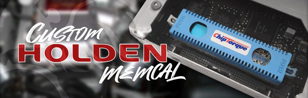
Holden memcals are programmed from the factory with very specific configurations. They are programmed for parameters such as: engine size, intake size, exhaust flow rate, fuel injector size and type, sensor configuration, transmission controls, dashboard data and everything that the computer controls to make it all run correctly together. Each memcal matches it’s ECU counterpart with a 4 letter designation (eg. CJKM).
We have seen many ‘eBay’ type units sold as performance chips but when read, they only have a stock Holden file.
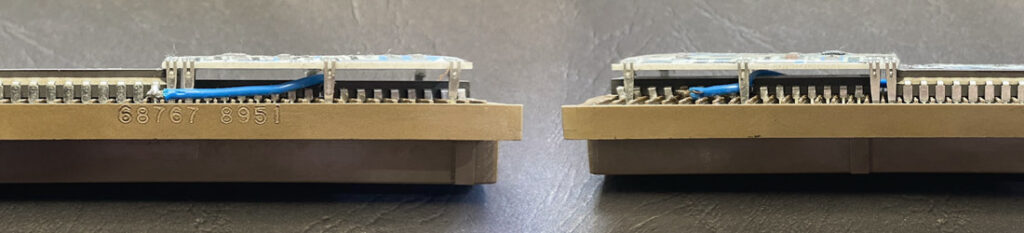
Look out for bridge links soldered between the EEPROM and knock board, this usually indicates a V6 memcal being used as a HSV unit. This “hack” will allow the injectors to function as per the V8 memcal however the knock boards are not like for like. It may work partially but not correctly.

+5V Supply – C
MAP Signal – B
Sensor Ground – A
5Volts – Pin B7 (Alternatively pin A7 from TPS)
Signal – Pin B10 (Add)
Sensor GND – Pin F16 (Alternatively pin E16 from TPS)
5Volts – Pin B7 (EGR (D) Violet/White)
Signal – Pin B10 (EGR (C) Light Green)
Sensor GND – Pin F16 (EGR (B) Black)
Leave EGR 5pin plug disconnected
5Volts – Pin C16 (EGR (D) Violet/White)
Signal – Pin C8 (EGR (C) Light Green)
Sensor GND – Pin D6 EGR (B) Black)
Leave EGR 5pin plug disconnected
5Volts – Pin B7 (EGR (D) Violet/White) (alternative pinA7)
Signal – Pin B10 (EGR (C) Light Green)
Sensor GND – Pin F16 (EGR (B) Black) (alternative pinE16)
5Volts – Pin C16 (EGR (D) Violet/White)
Signal – Pin C8 (EGR (C) Light Green)
Sensor GND – Pin B5 (EGR (B) Black)
Leave EGR 5pin plug disconnected
5Volts – Pin B7 (EGR (D) Violet/White) (alternative pinA7)
Signal – Pin B10 (EGR (C) Light Green)
Sensor GND – Pin F16 (EGR (B) Black) (alternative pinE16)
5Volts – Pin B7
Signal – Pin B10
Sensor GND – Pin F16
5Volts – Pin B7
Signal – Pin B10
Sensor GND – Pin F16
The Ezy-FLASH Pro allows you to store a library of modified tunes, enabling quick and easy ‘flashing’ of your car’s engine control unit to increase performance, drivability and support aftermarket modifications. The plug-in unit can read and clear trouble codes, record high speed logs, display live data and performance metrics. The factory tune is also stored within the unit so that the car can be returned to stock at any time.
The Ezy-FLASH Pro must NEVER be used by the driver while the vehicle is in motion! Doing so is illegal, and is a danger to you, your vehicle, and others.
NEVER drive your vehicle with any cables connected (including Ezy-FLASH Pro cables) that may interfere with vehicle controls.
Reflashing your vehicle with the Ezy-FLASH Pro unit may void all or part of your manufacturer’s warranty. Other than product quality guarantee, there are no guarantees with the Ezy-FLASH Pro, either express or implied by ChipTorque or any Ezy-FLASH Pro dealers. The user accepts all risks and responsibilities when using the Ezy-FLASH Pro.
Ensure your vehicle battery is fully charged and its condition is good before beginning any reflashing process, including changing maps, locking, and unlocking the Ezy-FLASH Pro. Reflashing with insufficient battery energy may cause a reflash error, which may damage your ECU and prevent your vehicle from starting.
DO NOT disturb the vehicle, cables, or ECU during the reflashing process, including changing maps, locking, and unlocking the Ezy-FLASH Pro. Interrupting the reflash process may cause a reflash error, which may damage your ECU and prevent your vehicle from starting.
DO NOT attempt any repairs on the Ezy-FLASH Pro unit. No user-serviceable parts inside. In the unlikely event of an Ezy-FLASH Pro device failure, contact the place of purchase and return the unit to them for repairs.
You get a whole set of tuning maps included when you purchase the Ezy-FLASH Pro product. Exactly which ones you get depend on the vehicle type, and it’s modifications. Usually you will get at least the following maps bundled with your Ezy-FLASH Pro:
Additional Tune Sets can be purchased from ChipTorque directly.
The Ezy-FLASH Pro unit is programmed with the latest firmware available at the time of manufacture. It is possible that a newer version is available, and it is recommended that you always use the latest available version.
NOTE: Some updates require the Ezy-FLASH Pro to be unlocked before updating. If so, Tune Manager will inform you. If your Ezy-FLASH Pro is locked to your vehicle, you will need to follow the unlocking procedure.
It is also possible that some refinements are made to the menu structure from version to version. This may mean that the examples shown in this User Manual do not correlate exactly to your Ezy-FLASH Pro unit.
Ensure your vehicle battery is fully charged and its condition is good before beginning any reflashing process, including changing maps, locking, and unlocking the Ezy-FLASH Pro. To minimise the power drain from the battery during reflashing operations, we recommend you turn off all accessories, including lights, entertainment systems / radios, fans / air conditioner, etc. As an extra precaution, an external battery charger may be added to the vehicle, although this is normally unnecessary with a healthy, charged battery.
Note: Tuning Programs are sometimes called Tunes, ROMs, or Maps. These terms may be used interchangeably in this document. The exact text shown on the LCD windows in this document may differ from those on your Ezy-FLASH Pro screen.
Note: The first time you connect your Ezy-FLASH Pro to your vehicle, the Ezy-FLASH Pro must establish a partnership with your vehicle (“Locking”). During this phase, the Ezy-FLASH Pro will query the vehicle type and check that it is compatible with the Tune you have selected. It will then read and verify the maps in the ECU (“Initial Tune”), so your vehicle can be unlocked and fully returned to it’s original program if desired.
DO NOT DISTURB the Ezy-FLASH Pro, cables, or vehicle during the reflashing or locking process. Doing so may render your vehicle inoperable. This event is not warranted.
Note: Trouble Codes are also known as “Diagnostic Trouble Codes”, or “DTCs” for short. Most modern vehicles, including Subaru, store two sets of DTCs – Current and Historic. Current codes indicate problems that the vehicle still experiencing. Historic codes indicate a problem that has happened in the past, but is not exhibiting itself presently.
Subaru vehicles clear historic and current DTCs by resetting the ECU. This has an unfortunate side effect; it also clears all other learned data in the ECU. One of these parameters – the Ignition Advance Multiplier - controls additional timing advance, and when it is reset, your vehicle may temporarily lose significant power (up to around 20wkW). All of this data will be re-learned over time and your vehicle performance will improve accordingly.
You can view up to 4 parameters at a time live (in real-time) using this feature. Data logging can be used on any compatible vehicle, not only the ‘locked’ vehicle.
DO NOT view live data while driving on road.
Note: Data parameters may differ from those shown. Most versions may support multiple screens of live data. Scroll through screens using UP and DOWN buttons. Some parameters may not be available on all vehicle types. In this case alternate parameters may be used, or the allocated space will remain blank.
Below is a list of parameters that may be available when using Live Data View.
NOTE: Some parameters may not be available for all vehicles.
Some values are displayed in Metric or Imperial units. Select your preferred Units System from the Setup menu.
RPM | Engine Speed in Revs Per Minute |
LI | Learned Ignition Timing. The amount of timing advance added by the ECU’s learning table to the base timing. Negative values retard timing. (°) |
KC | Knock Correction Advance. Equivalent to Learned Ignition Timing (°) |
MAP | Manifold Absolute Pressure |
Inj | Injector (1) duty cycle (%) |
WGD | Turbo Wastegate Solenoid duty cycle (%) |
Ld | Engine Load (relative %) |
MAF | Mass Air Flow (grams/second) |
AFR | Air/Fuel ratio |
AFC | Air/Fuel Correction (%). |
AFL | Air/Fuel Learning (%) |
Spk | Spark Advance / Ignition Total Timing (° BTDC) |
VSS | Vehicle Speed Sensor |
TPS | Throttle Position Sensor (%) |
APP | Accelerator Pedal Position (%). DBW vehicles only |
Vb | Battery voltage |
IAT | Intake Air Temperature |
Parameters displayed using Live Data View are for information only. ChipTorque accepts no responsibility for damage arising from inaccurate or misleading parameter data.
You can select which parameters are logged using High-Speed Data Logging. Use Tune Manager to set up these parameters. If no parameters are specified, a default set of parameters will be used. Data logging can be used on any compatible vehicle, not only the ‘locked’ vehicle.
The Ezy-FLASH Pro allocates 10Mb for data logging. Depending on the number of parameters selected and the vehicle type, this may give a total continuous logging time of approximately 3 to 20 days.
Note: This section is only relevant for people who wish to use their Ezy-FLASH Pro with multiple vehicles with different ECU styles. An example of when this may occur is if the Ezy-FLASH Pro is sold to a user with a different vehicle type or year model.
The Ezy-FLASH Pro is supplied with the ability to function fully with any supported Subaru vehicle.
There are 3 Subaru ECU styles supported by Ezy-FLASH Pro. Ezy-FLASH Pro comes pre-installed with a single license which may be applied to either ECU style. This license applies to the first vehicle type the Ezy-FLASH Pro t is locked to. Ezy-FLASH Pro can be used on any other vehicles that have the same ECU style.
Before the Ezy-FLASH Pro can be used on vehicles with a different ECU style, a new license must be installed. Contact your Ezy-FLASH Pro supplier for information on purchasing additional licenses if required.
The 3 supported Subaru ECU Styles belong in the following vehicles groups:
The year model overlaps are a guide only, since this varies between sales regions.
The Ezy-FLASH Pro is designed to operate at between 0°C and 40°C (32°F-104°F) at less than 90% relative humidity, although the display contrast may suffer at the extremes of this temperature range.
Using the Ezy-FLASH Pro outside of this temperature range may cause damage to the unit, and/or may cause it to not operate correctly. Never leave or store the Ezy-FLASH Pro in direct sunlight! Recommended storage temperature is –20°C-50°C (0°F-122°F).
Do not use the Ezy-FLASH Pro if the relative humidity is above 90%. DO NOT allow the Ezy-FLASH Pro to get wet!!!
The Ezy-FLASH Pro unit is not air-tight. In very cold or humid environments there is a likelihood that condensation will form inside the unit; you would see this as dew on the display window.
It is not advisable to reflash your vehicle when condensation exists inside the unit as this may affect the electronics.
Handle the Ezy-FLASH Pro with care. Do not subject the Ezy-FLASH Pro or any of its related parts to excessive shock or vibration, including dropping the unit.
Do not store the Ezy-FLASH Pro where it may be subject to strong vibration, extremes of moisture (> 90% humidity), extreme temperatures, or places that may expose it to direct sunlight.
Clean the outside of the Ezy-FLASH Pro with a soft cloth and mild detergent or cleaning spirit/methylated spirits/denatured alcohol. Do not allow fluid to run inside the case.
Excessive pressure and rubbing may cause damage to the exterior of the Ezy-FLASH Pro.
Do not attempt to open the Ezy-FLASH Pro unit! Doing so will not only void the factory warranty, it also puts the internal circuitry at risk of damage from static shock, among other things. There are no user-serviceable parts inside.
Symptom | Probable Causes & Solutions |
Cannot connect (locking, reflashing, or unlocking) |
|
Cannot connect (DTCs, data logging) |
|
Reflash failed |
|
Vehicle not recognised |
|
The benefits provided by this Warranty are in addition to all other rights and remedies in respect of the product which the consumer has under the Trades Practices Act 1974 and/ or any other State and Territory Laws. The original purchaser of the ChipTorque product is provided with the following Warranty subject to the Warranty Conditions:
ChipTorque warrants this product for all parts defective in workmanship or materials for the period of 12 months.
DBW | Drive-By-Wire, where the accelerator pedal is not directly connected to the throttle plate. Instead, the throttle plate angle is controlled electronically by the ECU. |
DTC | Diagnostic Trouble Code. DTCs are stored in the vehicle’s ECU if it detects a problem in the vehicle system. Each code is unique and corresponds to a specific problem. |
Dynamometer | “Dyno”. Equipment for measuring power and torque output of a vehicle (“chassis dyno”) or an engine (“engine dyno”). |
ECU | Engine Control Unit. A computer that controls delivery of fuel, timing of spark, and many other parameters to make an engine operate. |
Flash | Flash memory. Stores the tuning maps (and other engine control code) in the ECU. |
Initial ROM | The control code that existed in your ECU before the Ezy-Flash was introduced. |
wKw | Wheel Kilowatts. The power produced at the wheels. This is the power at the flywheel less transmission and drivetrain losses. |
Reflash | To reprogram the tuning maps and engine control code in the ECU. |
ROM | “Read Only Memory”. In this context, ROM describes a computer program that alters the tuning maps in a vehicle. Also called a ‘Tune’. |
TC | Throttle Cable. ‘Conventional’ throttle control where accelerator pedal is directly connected to the throttle blade using a cable. Opposite to DBW. |
TMC | Test Mode Connector. Used to initiate reflash mode in many vehicles. |
TMSA | Test Mode Switch Assembly. Provides convenient access to Test Mode Connectors. |
Tune | A computer program that alters the tuning maps in a vehicle. Also called a ‘ROM’. |
Tune Bank | A collection of Tune Sets. |
Tune Set | A set of tunes which apply to a single vehicle type. |
Tuning Maps | Data tables that describe to the ECU the correct amount of a physical quantity (i.e., fuel, ignition timing, turbo boost pressure) to apply to a vehicle under a predefined set of conditions (e.g., engine speed, engine load, requested throttle / torque, ambient conditions, etc). |
The base timing should be set to (factory recommended) 10degrees BTDC with timing light and can be checked / set at any RPM below 2,000rpm in diagnostic mode.
You can check you are correctly in the diagnostic mode if there is no CEL etc. by testing that: above the 2,000rpm point, the timing will change from a fixed value 10Deg BTDC to normal variable timing of more than 30Deg BTDC. As the RPM is reduced to below 2000rpm again, it will return to the fixed setting value that should be 10deg BTDC.
Hint: For large cams or lumpy idle applications, raise the engine RPM to 1,500rpm with an assistant or feeler gauges under the throttle stop screw to reduce timing “shake” while setting it. Remember to keep RPM below 2,000rpm while setting the timing.
V6 engines have no timing to set.
VN – VP V8
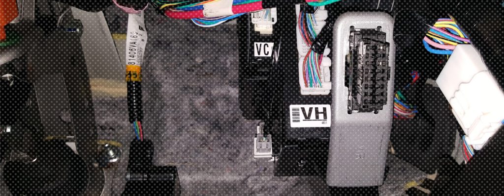
Link pins in the ALDL connector (white square plug on wiring loom approximately 15cm from ECU on the main engine harness). At one end of the ALDL connector link 2 wires above and below one another (black with white trace and white with black trace). ChipTorque recommends a very fine metal paperclip or split pin as the best tool to use. If the link is correct, with the engine running the check engine light will now flash on and off about once per second.
VR – VT V8
Link pin 5 (black with white trace wire or straight black wire) and pin 6 (white with black trace wire) on the 16pin OBD diagnostic plug under the steering wheel at the bottom of the trim panel. ChipTorque recommend a very fine metal paperclip or split pin as the best tool to use. If the link is correct, with the engine running the check engine light will now flash on and off about once per second.
No Diagnostic Plug
If the engine is transplanted and the OBD / ALDL plug is not available, connect the Diagnostic request wire (white with black trace wire) to ground. Diagnostic Request wire:
VN – VP All ECU pin A9
VR – VS Manual ECU pin A9
VR – VS Auto PCM pin D6
VSIII or VT V8 PCM pin F14
If the ECU has been removed, or battery power has been disconnected, the first start will require an idle relearn including IAC reset. The ECU will do this automatically on first start once the engine RPM exceeds 2,500rpm for greater than 4 seconds.
To start the process manually:
To complete the idle relearn:
If a scan tool is available:
If no scan tool is available:
Make small incremental adjustments as required with ignition OFF and allow the idle to relearn each time as described above.
As a guide: With the IAC passage fully blocked off (temporarily, with tape or a finger) the idle screw should be set to achieve an idle approximately 50-100RPM less than the “Desired Idle” speed set in the Chip; (call ChipTorque with your Chip Serial Number for application specifics if you are not sure).