
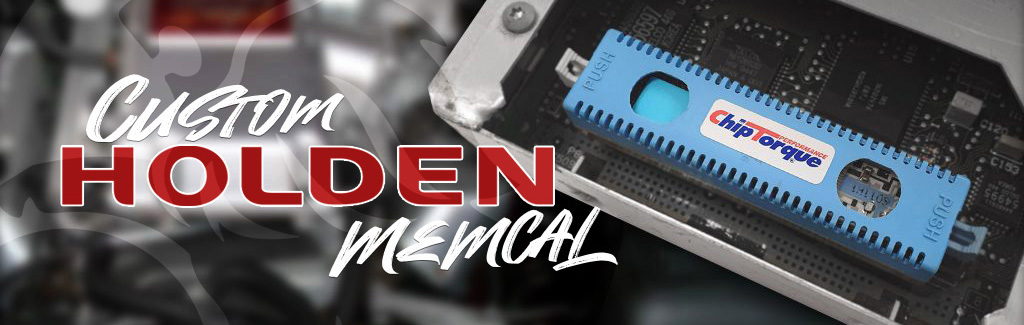
Holden memcals are programmed from the factory with very specific configurations. They are programmed for parameters such as: engine size, intake size, exhaust flow rate, fuel injector size and type, sensor configuration, transmission controls, dashboard data and everything that the computer controls to make it all run correctly together. Each memcal matches it’s ECU counterpart with a 4 letter designation (eg. CJKM).
We have seen many ‘eBay’ type units sold as performance chips but when read, they only have a stock Holden file.
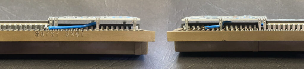
Look out for bridge links soldered between the EEPROM and knock board, this usually indicates a V6 memcal being used as a HSV unit. This “hack” will allow the injectors to function as per the V8 memcal however the knock boards are not like for like. It may work partially but not correctly.

+5V Supply – C
MAP Signal – B
Sensor Ground – A
5Volts – Pin B7 (Alternatively pin A7 from TPS)
Signal – Pin B10 (Add)
Sensor GND – Pin F16 (Alternatively pin E16 from TPS)
5Volts – Pin B7 (EGR (D) Violet/White)
Signal – Pin B10 (EGR (C) Light Green)
Sensor GND – Pin F16 (EGR (B) Black)
Leave EGR 5pin plug disconnected
5Volts – Pin C16 (EGR (D) Violet/White)
Signal – Pin C8 (EGR (C) Light Green)
Sensor GND – Pin D6 EGR (B) Black)
Leave EGR 5pin plug disconnected
5Volts – Pin B7 (EGR (D) Violet/White) (alternative pinA7)
Signal – Pin B10 (EGR (C) Light Green)
Sensor GND – Pin F16 (EGR (B) Black) (alternative pinE16)
5Volts – Pin C16 (EGR (D) Violet/White)
Signal – Pin C8 (EGR (C) Light Green)
Sensor GND – Pin B5 (EGR (B) Black)
Leave EGR 5pin plug disconnected
5Volts – Pin B7 (EGR (D) Violet/White) (alternative pinA7)
Signal – Pin B10 (EGR (C) Light Green)
Sensor GND – Pin F16 (EGR (B) Black) (alternative pinE16)
5Volts – Pin B7
Signal – Pin B10
Sensor GND – Pin F16
5Volts – Pin B7
Signal – Pin B10
Sensor GND – Pin F16
The base timing should be set to (factory recommended) 10degrees BTDC with timing light and can be checked / set at any RPM below 2,000rpm in diagnostic mode.
You can check you are correctly in the diagnostic mode if there is no CEL etc. by testing that: above the 2,000rpm point, the timing will change from a fixed value 10Deg BTDC to normal variable timing of more than 30Deg BTDC. As the RPM is reduced to below 2000rpm again, it will return to the fixed setting value that should be 10deg BTDC.
Hint: For large cams or lumpy idle applications, raise the engine RPM to 1,500rpm with an assistant or feeler gauges under the throttle stop screw to reduce timing “shake” while setting it. Remember to keep RPM below 2,000rpm while setting the timing.
V6 engines have no timing to set.
VN – VP V8
Link pins in the ALDL connector (white square plug on wiring loom approximately 15cm from ECU on the main engine harness). At one end of the ALDL connector link 2 wires above and below one another (black with white trace and white with black trace). ChipTorque recommends a very fine metal paperclip or split pin as the best tool to use. If the link is correct, with the engine running the check engine light will now flash on and off about once per second.
VR – VT V8
Link pin 5 (black with white trace wire or straight black wire) and pin 6 (white with black trace wire) on the 16pin OBD diagnostic plug under the steering wheel at the bottom of the trim panel. ChipTorque recommend a very fine metal paperclip or split pin as the best tool to use. If the link is correct, with the engine running the check engine light will now flash on and off about once per second.
No Diagnostic Plug
If the engine is transplanted and the OBD / ALDL plug is not available, connect the Diagnostic request wire (white with black trace wire) to ground. Diagnostic Request wire:
VN – VP All ECU pin A9
VR – VS Manual ECU pin A9
VR – VS Auto PCM pin D6
VSIII or VT V8 PCM pin F14
If the ECU has been removed, or battery power has been disconnected, the first start will require an idle relearn including IAC reset. The ECU will do this automatically on first start once the engine RPM exceeds 2,500rpm for greater than 4 seconds.
To start the process manually:
To complete the idle relearn:
If a scan tool is available:
If no scan tool is available:
Make small incremental adjustments as required with ignition OFF and allow the idle to relearn each time as described above.
As a guide: With the IAC passage fully blocked off (temporarily, with tape or a finger) the idle screw should be set to achieve an idle approximately 50-100RPM less than the “Desired Idle” speed set in the Chip; (call ChipTorque with your Chip Serial Number for application specifics if you are not sure).